Project overview
The purpose of this circuit was to allow board members to cast their ballots and have it display the pass or fail status of the decision using an electronic voting machine. The board consisted of four members, the president, vice president, secretary and a treasurer.Some constraints of the design included only using two-input gates and that if the vote ever came to a tie then the presidents vote would break the tie.
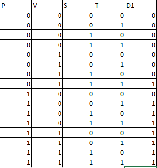
Truth table & Un-simplified expression
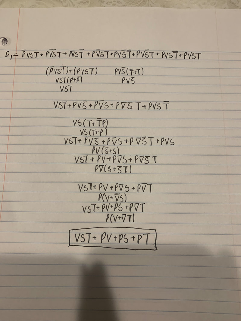
[D1= P'VST+PV'S'T+PV'ST'+PV'ST+PVS'T'+PVS'T+PVST'+PVST ]
D1 simplified equals "VST+PV+PS+PT" |
The truth table is a simple list of all the combinations and outcomes.The project had 4 variables in it, including the president, vice president, secretary and treasurer meaning there was gonna be a total of 16 rows in the truth table. In our truth table we used ones to represent a "yes" vote, and zeros as a "No" vote.If the decision was passed then there would be a one in the last column (D). In the case of a tie between two people the president would have to vote to make the final decision. Using this Truth table it allows us to see the outcome of all their decisions, and gives us an un-simplified equation.
The un-simplified equation is in (SOP) or sum of products format. Our un-simplified equation had a total of 8 different combinations.In these combinations if the person had voted yes then the variable was left alone, however if the person had voted no then this would be represented with a line above the variable. I arrived at each minterm when the president and another person voted and when three fourths of the directors had voted yes. SOP form is better then POS form because it shows the individual combinations that come from the truth table allowing the decision to pass.
|
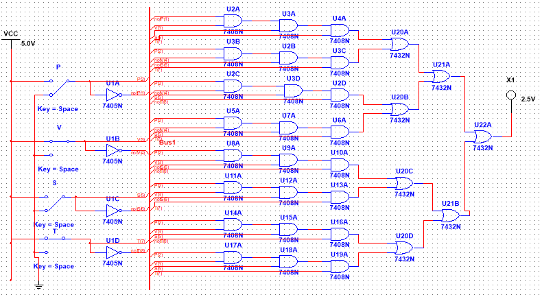
Un-simplified circut
|
I used bus form to create my circuit so that it would be organized and efficient. I used the bus method because it made finding problems within the circuit easier. When i completed my circuit i used 4 inverters, 24 AND gates,and 7 OR gates. Inverters changed the variable from a X to a "not" X. The AND gates used could only multiply two variables, while the OR gates added the variables together. The number of gates required was 4, meaning i would have 9 chips in total.
|
Boolean Algebra
Boolean algebra was used to simplify the un-simplified equation we had from the truth table. The simplified expression would make it easier for us to create a simplified circuit later on. This would make the circuit easier to wire on a breadboard and would use less gates in total.
Simplified circuit
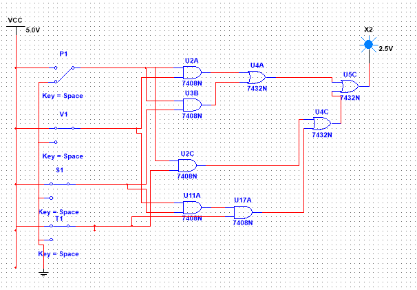
For the simplified circuit i didn't use the bus method. This circuit was very simple and didn't have to use as many gates as the un-simplified circuit did, meaning any mistakes could be recognized faster then in the un-simplified. In this simplified circuit there was no need for inverters because the simplified equation had all "yes" votes and didn't have any "no" votes. This simplified equation also lowered the amount of gates from 8 to 3 chips.
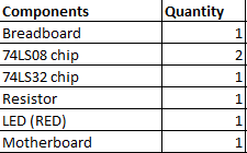
Bill of materials
|
The bill of materials states the amount of required materials that was needed to create a working circuit.
|
Majority Vote Circuit Bill of Materials.
|
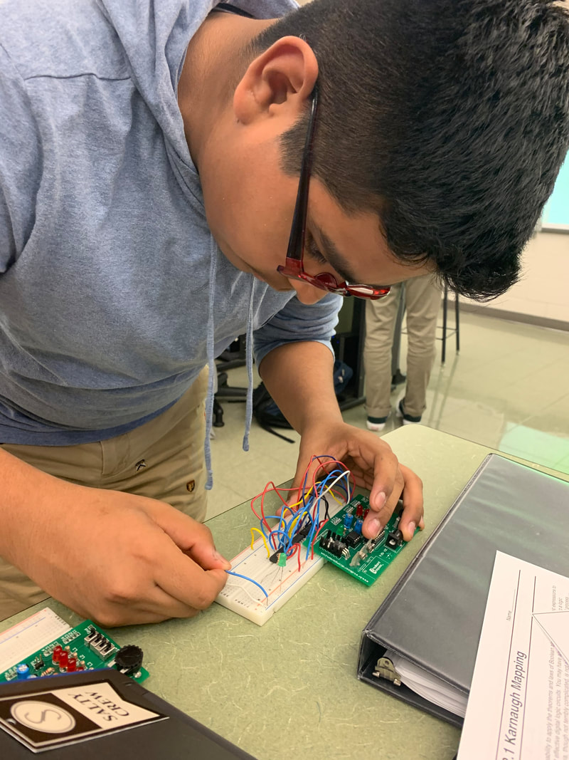
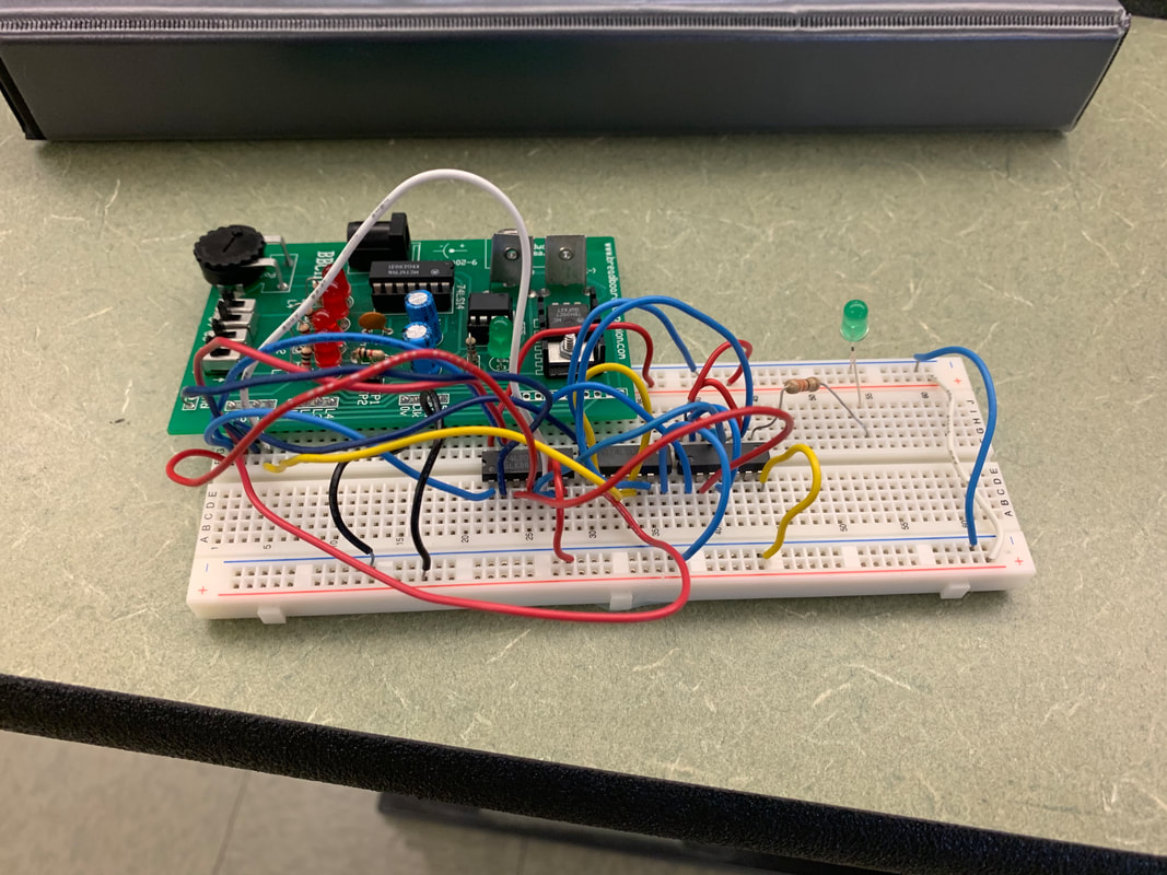
Bread-Boarding
|

|
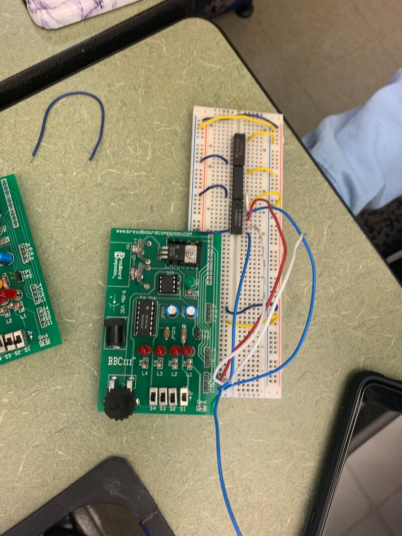
In the first photo on the top left corner is my circuit fully completed with the circuit working perfectly fine. The top right photo is my circuit in the very beginning when i had placed my IC chips into my bread board. The third photo is my circuit halfway through completion,and i had just connected my chips to positive and negative while connecting my variables to the AND/OR gates.
My first bread-boarding experience was really tough. I had lots of trouble when first starting the circuit but over the next few days some people helped explain most of it to me making it a little easier to create. Some mistakes that made were not connecting the resistor to the 74LS32 chip. Another mistake i made was forgetting to ground my circuit. Some troubleshooting i had to do was making sure my IC chips were pushed far enough into the circuit and that my LED worked. I learned that color coding can help organize the circuit greatly.
Project Conclusions
Some important take-away's from this project is that i need to work harder with creating breadboards so that i can understand it better and create a circuit without many problems. This project showed me a lot about creating circuits and how easily it can be ruined with one wire, chip or LED not working. It also showed me that organization, color coding, and time use are very important factors when creating your circuit. From the problem statement i was able to create a truth table, and this allowed me to make an un-simplified expression. From this expression i simplified it using boolean algebra, to create an even simpler circuit. Boolean algebra was very useful because it allowed me to simplify the big complicated circuit i had originally created. This simplified circuit made it even easier to bread board.
